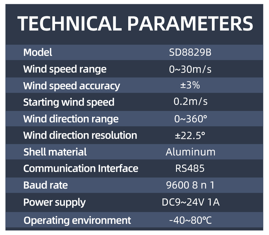
Technical Parameters
| Technical parameter | Parameter value |
| Brand | SONBEST |
| Wind speed range | 0~30m/s |
| Start wind | 0.2m/s |
| Wind speed accuracy | ±3% |
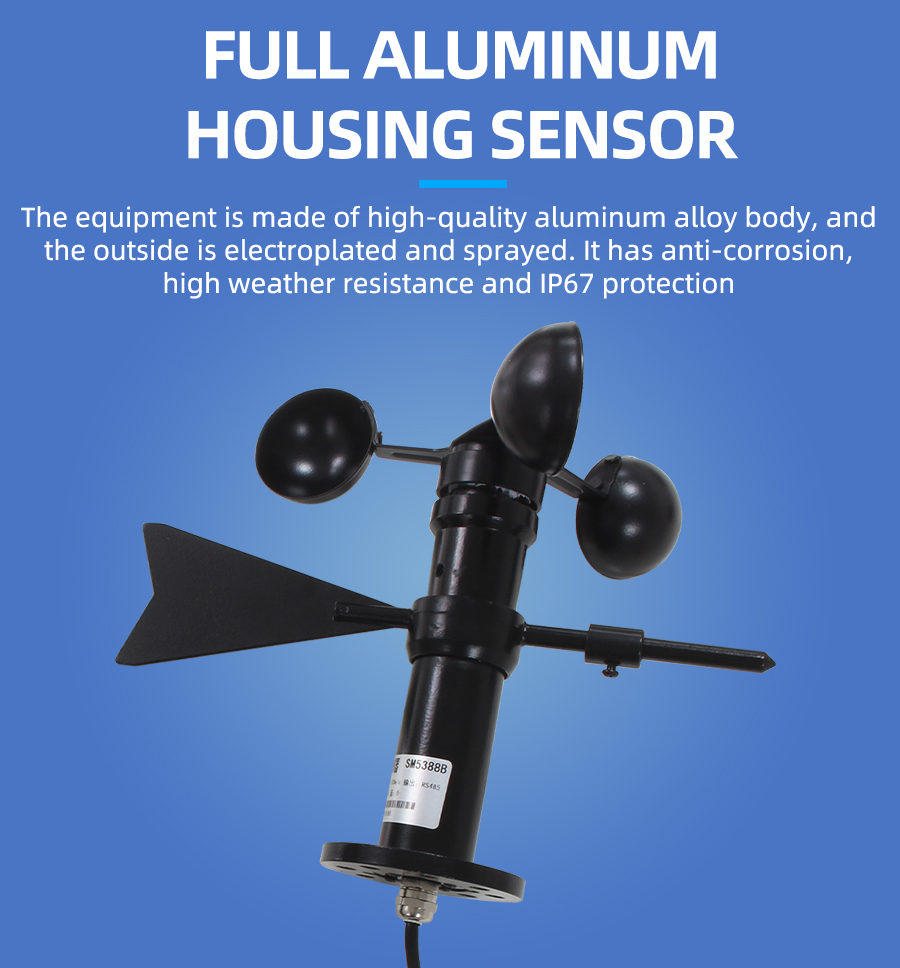
| Shell material | aluminum |
| Wind direction range | 0~360° |
| Wind direction resolution | 22.5° |
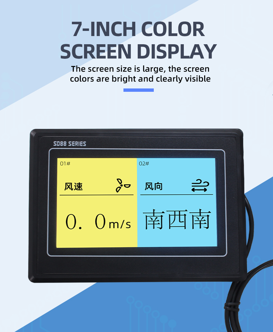
| Interface | RS485/4-20mA/DC0-5V/DC0-10V |
| Power | DC12~24V 1A |
| Running temperature | -40~80°C |
| Working humidity | 5%RH~90%RH |
Product Selection
Product DesignRS485,4-20mA,DC0-5V,DC0-10VMultiple output methods, the products are divided into the following models depending on the output method.
| Product model | output method |
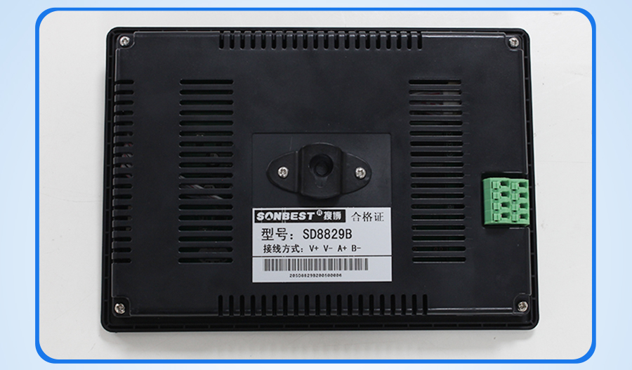
| SD8829B | RS485总线 |
| SD8829M | 4-20mA |
| SD8829V5 | DC0-5V |
| SD8829V10 | DC0-10V |
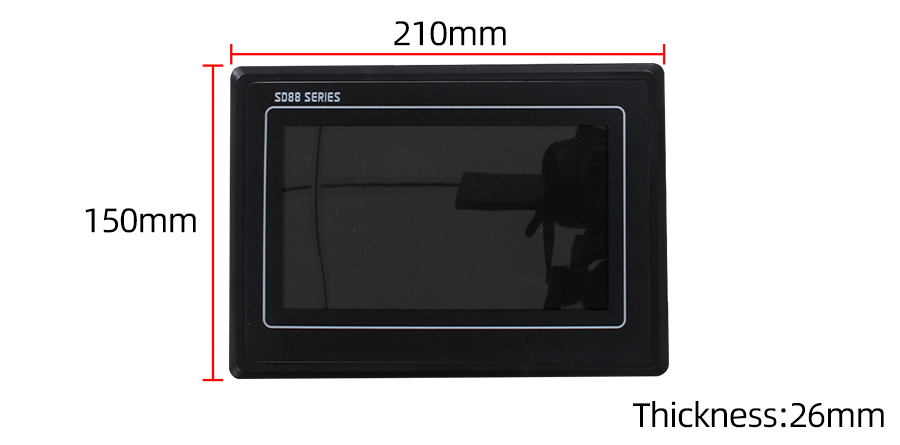
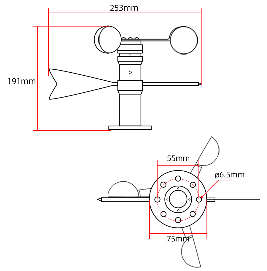
Product Size
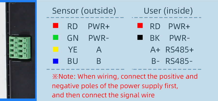
How to wiring?
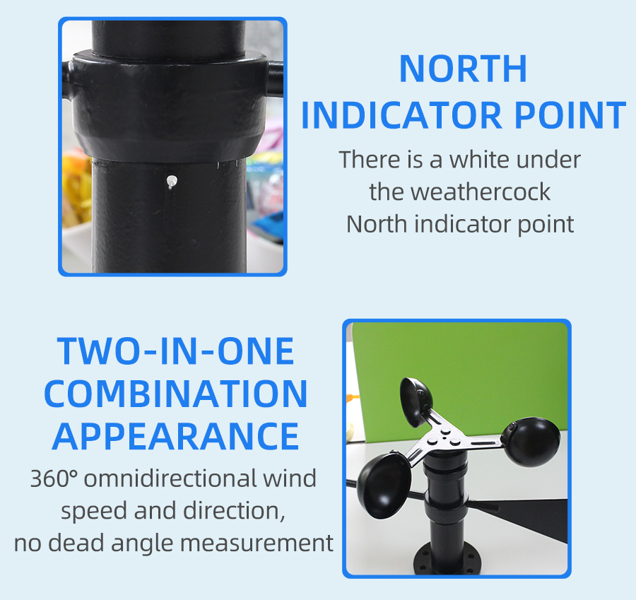
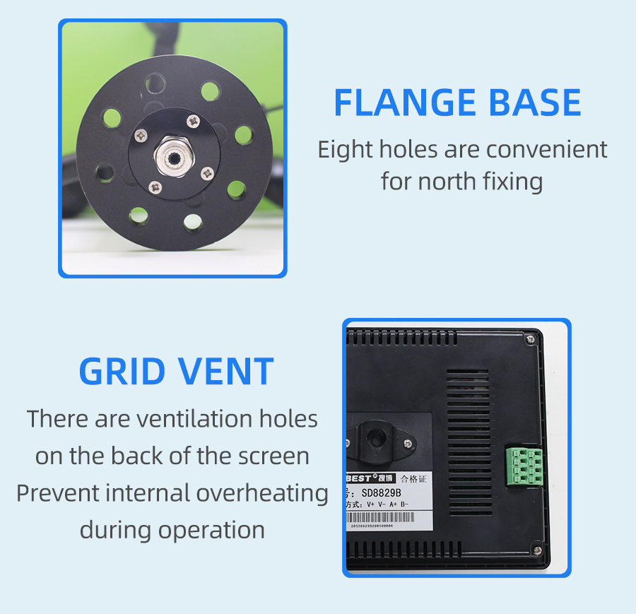
Why choose this product?
Application solution


How to use?

1. wind speed and current computing relationship
For example, the range is 0~30m/s, the analog output is 4~20mA current signal, wind speed and current The calculation relationship is as shown in the formula: C = (A2-A1) * (X-B1) / (B2-B1) + A1, where A2 is wind speed range upper limit, A1 is the lower limit of the range, B2 is current output range upper limit, B1 is the lower limit, X is the currently read wind speed value, and C is the calculated current value. The list of commonly used values is as follows:
| current(mA) | wind speedValue (m/s) | Calculation Process |
| 4 | 0.0 | (30-0)*(4-4)÷(20-4)+0 |
| 5 | 1.9 | (30-0)*(5-4)÷(20-4)+0 |
| 6 | 3.8 | (30-0)*(6-4)÷(20-4)+0 |
| 7 | 5.6 | (30-0)*(7-4)÷(20-4)+0 |
| 8 | 7.5 | (30-0)*(8-4)÷(20-4)+0 |
| 9 | 9.4 | (30-0)*(9-4)÷(20-4)+0 |
| 10 | 11.3 | (30-0)*(10-4)÷(20-4)+0 |
| 11 | 13.1 | (30-0)*(11-4)÷(20-4)+0 |
| 12 | 15.0 | (30-0)*(12-4)÷(20-4)+0 |
| 13 | 16.9 | (30-0)*(13-4)÷(20-4)+0 |
| 14 | 18.8 | (30-0)*(14-4)÷(20-4)+0 |
| 15 | 20.6 | (30-0)*(15-4)÷(20-4)+0 |
| 16 | 22.5 | (30-0)*(16-4)÷(20-4)+0 |
| 17 | 24.4 | (30-0)*(17-4)÷(20-4)+0 |
| 18 | 26.3 | (30-0)*(18-4)÷(20-4)+0 |
| 19 | 28.1 | (30-0)*(19-4)÷(20-4)+0 |
| 20 | 30.0 | (30-0)*(20-4)÷(20-4)+0 |
2. conductivity and current computing relationship
For example, the range is 0~360°, the analog output is 4~20mA current signal, conductivity and current The calculation relationship is as shown in the formula: C = (A2-A1) * (X-B1) / (B2-B1) + A1, where A2 is conductivity range upper limit, A1 is the lower limit of the range, B2 is current output range upper limit, B1 is the lower limit, X is the currently read conductivity value, and C is the calculated current value. The list of commonly used values is as follows:
| current(mA) | conductivityValue (°) | Calculation Process |
| 4 | 0.0 | (360-0)*(4-4)÷(20-4)+0 |
| 5 | 22.5 | (360-0)*(5-4)÷(20-4)+0 |
| 6 | 45.0 | (360-0)*(6-4)÷(20-4)+0 |
| 7 | 67.5 | (360-0)*(7-4)÷(20-4)+0 |
| 8 | 90.0 | (360-0)*(8-4)÷(20-4)+0 |
| 9 | 112.5 | (360-0)*(9-4)÷(20-4)+0 |
| 10 | 135.0 | (360-0)*(10-4)÷(20-4)+0 |
| 11 | 157.5 | (360-0)*(11-4)÷(20-4)+0 |
| 12 | 180.0 | (360-0)*(12-4)÷(20-4)+0 |
| 13 | 202.5 | (360-0)*(13-4)÷(20-4)+0 |
| 14 | 225.0 | (360-0)*(14-4)÷(20-4)+0 |
| 15 | 247.5 | (360-0)*(15-4)÷(20-4)+0 |
| 16 | 270.0 | (360-0)*(16-4)÷(20-4)+0 |
| 17 | 292.5 | (360-0)*(17-4)÷(20-4)+0 |
| 18 | 315.0 | (360-0)*(18-4)÷(20-4)+0 |
| 19 | 337.5 | (360-0)*(19-4)÷(20-4)+0 |
| 20 | 360.0 | (360-0)*(20-4)÷(20-4)+0 |
1. wind speed and voltage computing relationship
For example, the range is 0~30m/s, the analog output is 0~5V voltage signal, wind speed and voltage The calculation relationship is as shown in the formula: C = (A2-A1) * (X-B1) / (B2-B1) + A1, where A2 is wind speed range upper limit, A1 is the lower limit of the range, B2 is voltage output range upper limit, B1 is the lower limit, X is the currently read wind speed value, and C is the calculated voltage value. The list of commonly used values is as follows:
| voltage(V) | wind speedValue (m/s) | Calculation Process |
| 0 | 0.0 | (30-0)*(0-0)÷(5-0)+0 |
| 1 | 6.0 | (30-0)*(1-0)÷(5-0)+0 |
| 2 | 12.0 | (30-0)*(2-0)÷(5-0)+0 |
| 3 | 18.0 | (30-0)*(3-0)÷(5-0)+0 |
| 4 | 24.0 | (30-0)*(4-0)÷(5-0)+0 |
| 5 | 30.0 | (30-0)*(5-0)÷(5-0)+0 |
| 10 | 135.0 | (360-0)*(10-4)÷(20-4)+0 |
2. conductivity and voltage computing relationship
For example, the range is 0~360°, the analog output is 0~5V voltage signal, conductivity and voltage The calculation relationship is as shown in the formula: C = (A2-A1) * (X-B1) / (B2-B1) + A1, where A2 is conductivity range upper limit, A1 is the lower limit of the range, B2 is voltage output range upper limit, B1 is the lower limit, X is the currently read conductivity value, and C is the calculated voltage value. The list of commonly used values is as follows:
| voltage(V) | conductivityValue (°) | Calculation Process |
| 0 | 0.0 | (360-0)*(0-0)÷(5-0)+0 |
| 1 | 72.0 | (360-0)*(1-0)÷(5-0)+0 |
| 2 | 144.0 | (360-0)*(2-0)÷(5-0)+0 |
| 3 | 216.0 | (360-0)*(3-0)÷(5-0)+0 |
| 4 | 288.0 | (360-0)*(4-0)÷(5-0)+0 |
| 5 | 360.0 | (360-0)*(5-0)÷(5-0)+0 |
| 10 | 135.0 | (360-0)*(10-4)÷(20-4)+0 |
1. wind speed and voltage computing relationship
For example, the range is 0~30m/s, the analog output is 0~10V voltage signal, wind speed and voltage The calculation relationship is as shown in the formula: C = (A2-A1) * (X-B1) / (B2-B1) + A1, where A2 is wind speed range upper limit, A1 is the lower limit of the range, B2 is voltage output range upper limit, B1 is the lower limit, X is the currently read wind speed value, and C is the calculated voltage value. The list of commonly used values is as follows:
| voltage(V) | wind speedValue (m/s) | Calculation Process |
| 0 | 0.0 | (30-0)*(0-0)÷(10-0)+0 |
| 1 | 3.0 | (30-0)*(1-0)÷(10-0)+0 |
| 2 | 6.0 | (30-0)*(2-0)÷(10-0)+0 |
| 3 | 9.0 | (30-0)*(3-0)÷(10-0)+0 |
| 4 | 12.0 | (30-0)*(4-0)÷(10-0)+0 |
| 5 | 15.0 | (30-0)*(5-0)÷(10-0)+0 |
| 6 | 18.0 | (30-0)*(6-0)÷(10-0)+0 |
| 7 | 21.0 | (30-0)*(7-0)÷(10-0)+0 |
| 8 | 24.0 | (30-0)*(8-0)÷(10-0)+0 |
| 9 | 27.0 | (30-0)*(9-0)÷(10-0)+0 |
| 10 | 30.0 | (30-0)*(10-0)÷(10-0)+0 |
| 15 | 247.5 | (360-0)*(15-4)÷(20-4)+0 |
2. conductivity and voltage computing relationship
For example, the range is 0~360°, the analog output is 0~10V voltage signal, conductivity and voltage The calculation relationship is as shown in the formula: C = (A2-A1) * (X-B1) / (B2-B1) + A1, where A2 is conductivity range upper limit, A1 is the lower limit of the range, B2 is voltage output range upper limit, B1 is the lower limit, X is the currently read conductivity value, and C is the calculated voltage value. The list of commonly used values is as follows:
| voltage(V) | conductivityValue (°) | Calculation Process |
| 0 | 0.0 | (360-0)*(0-0)÷(10-0)+0 |
| 1 | 36.0 | (360-0)*(1-0)÷(10-0)+0 |
| 2 | 72.0 | (360-0)*(2-0)÷(10-0)+0 |
| 3 | 108.0 | (360-0)*(3-0)÷(10-0)+0 |
| 4 | 144.0 | (360-0)*(4-0)÷(10-0)+0 |
| 5 | 180.0 | (360-0)*(5-0)÷(10-0)+0 |
| 6 | 216.0 | (360-0)*(6-0)÷(10-0)+0 |
| 7 | 252.0 | (360-0)*(7-0)÷(10-0)+0 |
| 8 | 288.0 | (360-0)*(8-0)÷(10-0)+0 |
| 9 | 324.0 | (360-0)*(9-0)÷(10-0)+0 |
| 10 | 360.0 | (360-0)*(10-0)÷(10-0)+0 |
| 15 | 247.5 | (360-0)*(15-4)÷(20-4)+0 |
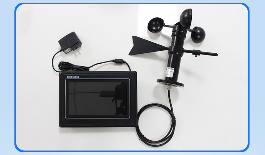
Product Pictures

Product Pictures