Technical Parameters
| Technical parameter | Parameter value |
| Brand | SONBEST |
| Temperature measurement range | -50°C to +100°C (optional with other ranges) |
| Detecting Core Devices | PT100 |
| Temperature Measurement Accuracy | ± 0.5°C (0.5FS) |
| Thermal Response Coefficient | 10mΩ/K |
| The resistance @ °C | 1000Ω±0.12Ω/K |
| The resistance rate | 0.385Ω/K |
| Reference Standards | Using EN 60751 Class B Standards |
| Channels | 8 |
| Communication Interface | CAN |
| Default rate | 50kbps |
| Power | DC9~24V 1A |
| Running temperature | -40~80°C |
| Working humidity | 5%RH~90%RH |
Wiring instructions
Any incorrect wiring can cause irreversible damage to the product. Please carefully wire the cable as follows in the case of power failure, and then connect the cable to confirm the correctness and then use it again.
| ID | Core color | Identification | Note |
| 1 | Red | V+ | Power V+ |
| 2 | Green | V- | Power V- |
| 3 | Yellow | H+ | CAN bus H+ |
| 4 | Blue | H- | CAN bus H- |
Communication Protocol
The product uses the CAN2.0B standard frame format. The standard frame information is 11 bytes including two parts of information and the first 3 bytes of the data part is the information part. The default node number of the device is 1, the report The text identification code is ID.10-ID.3 in the CAN standard frame, and the default rate is 50k. If other rates are required, it can be modified according to the communication protocol.
The device can work directly with various CAN converters or USB acquisition modules. Users can also choose our industrial grade USB-CAN converter (as shown above). The basic frame format and composition are as follows: The table shows.
| Bit | 7 | 6 | 5 | 4 | 3 | 2 | 1 | 0 |
| Byte 1 | FF | FTR | X | X | DLC.3 | DLC.2 | DLC.1 | DLC.0 |
| Byte 2 | ID.10 | ID.9 | ID.8 | ID.7 | ID.6 | ID.5 | ID.4 | ID.3 |
| Byte 3 | ID.2 | ID.1 | ID.0 | x | x | x | x | x |
| Byte 4 | d1.7 | d1.6 | d1.5 | d1.4 | d1.3 | d1.2 | d1.1 | d1.0 |
| Byte 5 | d2.7 | d2.6 | d2.5 | d2.4 | d2.3 | d2.2 | d2.1 | d2.0 |
| Byte 6 | d3.7 | d3.6 | d3.5 | d3.4 | d3.3 | d3.2 | d3.1 | d3.0 |
| Byte 7 | d4.7 | d4.6 | d4.5 | d4.4 | d4.3 | d4.2 | d4.1 | d4.0 |
| Byte 8 | d5.7 | d5.6 | d5.5 | d5.4 | d5.3 | d5.2 | d5.1 | d5.0 |
| Byte 9 | d6.7 | d6.6 | d6.5 | d6.4 | d6.3 | d6.2 | d6.1 | d6.0 |
| Byte 10 | d7.7 | d7.6 | d7.5 | d7.4 | d7.3 | d7.2 | d7.1 | d7.0 |
| Byte 11 | d8.7 | d8.6 | d8.5 | d8.4 | d8.3 | d8.2 | d8.1 | d8.0 |
1. Query data
Example: Query 1# device channel 1 all 2 data, the host computer sends the command: 01 03 00 00 00 02.
| Frame type | Frame ID | Set address | Function ID | Start Address | Data length |
| 00 01 | 01 | 01 | 03 | 00 00 | 02 |
| Byte 2 | ID.10 | ID.9 | ID.8 | ID.7 | ID.6 |
| ID.5 | ID.4 | ID.3 |
| Frame type | Frame ID | Set address | Function ID | Data length | Data |
| Response | 00 00 | 01 | 03 | 04 | 08 AD 0F 7D |
| Byte 2 | ID.10 | ID.9 | ID.8 | ID.7 | ID.6 |
| ID.5 | ID.4 | ID.3 |
2. Change Frame ID
You can use the master station to reset the node number by command. The node number ranges from 1 to 200. After resetting the node number, you must reset the system. Because the communication is in hexadecimal format, the data in the table Both are in hexadecimal format.
For example, if the host ID is 00 00 and the sensor address is 00 01, the current node 1 is changed to the 2nd. The communication message for changing the device ID is as follows: 01 06 0B 00 00 02.
| Frame type | Frame ID | Set Address | Function id | fixed value | target frame ID |
| Command | 00 01 | 01 | 06 | 0B 00 | 00 02 |
| Byte 2 | ID.10 | ID.9 | ID.8 | ID.7 | ID.6 |
| ID.5 | ID.4 | ID.3 |
| Frame ID | Set Address | Function id | source frame ID | current frame ID | CRC16 |
| 00 00 | 01 | 06 | 01 | 02 | 61 88 |
| Byte 2 | ID.10 | ID.9 | ID.8 | ID.7 | ID.6 |
| ID.5 | ID.4 | ID.3 |
3. Change device rate
You can use the master station to reset the device rate by command. The rate number range is from 1 to 11. After resetting the node number, the rate takes effect immediately. Because the communication is in hexadecimal format, the rate in the table. The numbers are all in hexadecimal format.
| rate number | rate | rate number | rate |
| 1 | 10kbps | 2 | 20kbps |
| 3 | 25kbps | 4 | 40kbps |
| 5 | 50kbps | 6 | 100kbps |
| 7 | 125kbps | 8 | 200kbps |
| 9 | 250kbps | A | 400kbps |
| B | 500kbps | C | 1M (unused) |
| Byte 7 | d4.7 | d4.6 | d4.5 |
| d4.4 | d4.3 | d4.2 | d4.1 |
| d4.0 | Byte 8 | d5.7 | d5.6 |
| d5.5 | d5.4 | d5.3 | d5.2 |
| d5.1 | d5.0 |
After the execution rate is modified, the rate will change immediately and the device will not return any value. At this time, the CAN acquisition device also needs to switch the corresponding rate to communicate normally.
4. Return frame ID and rate after power-on
After the device is powered on again, the device will return the corresponding Set Address and rate information. For example, after the device is powered on, the reported message is as follows: 01 25 01 05 D1 80.
| frame ID | Set Address | Function id | current frame ID | current rate | CRC16 |
| 00 00 | 01 | 25 | 00 01 | 05 | D1 80 |
| 3 | 25kbps | 4 | 40kbps |
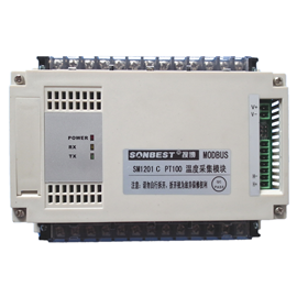
Product Pictures